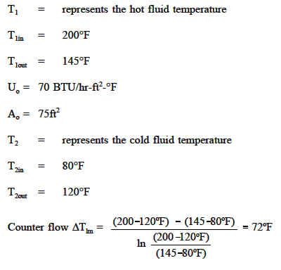
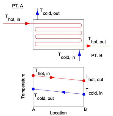
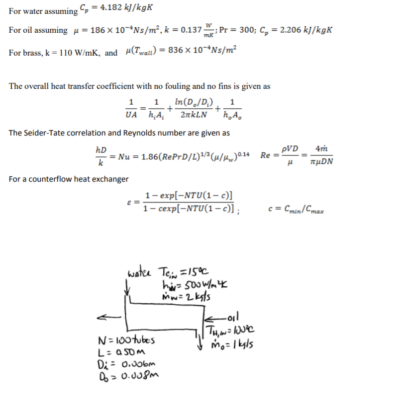
Counter Flow Heat Exchanger Equations
Comparison Of Heat Exchanger Types Parallel Heat Exchanger Cross Flow Heat Exchanger Counter Flow Heat Exchanger Engineers Edge
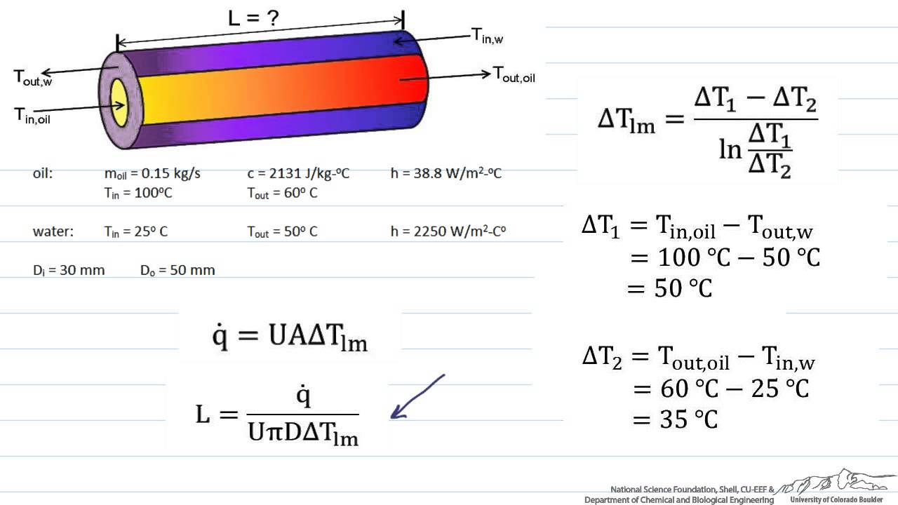
Sizing A Heat Exchanger Parallel Flow Youtube
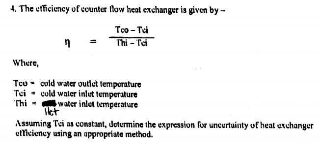
Solved The Efficiency Of Counter Flow Heat Exchanger Is G Chegg Com
18 5 Heat Exchangers
Parallel And Counter Flow Designs Heat Exchangers Engineers Edge Www Engineersedge Com
Why Is A Counter Flow Heat Exchanger Better Than A Parallel Flow Heat Exchanger Quora
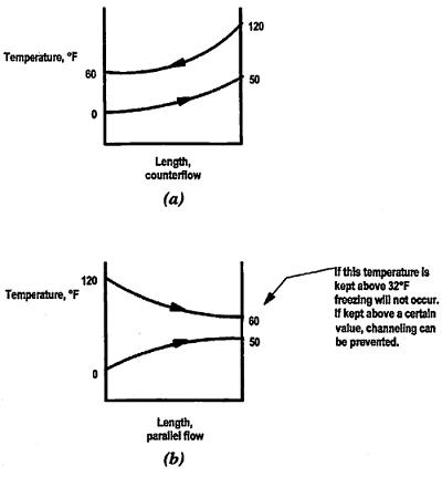
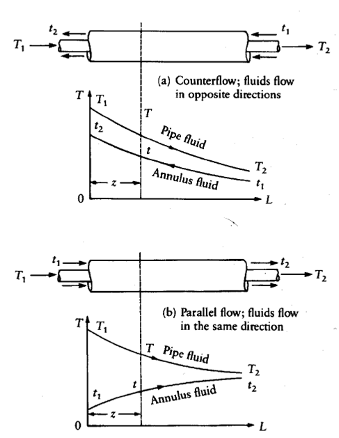
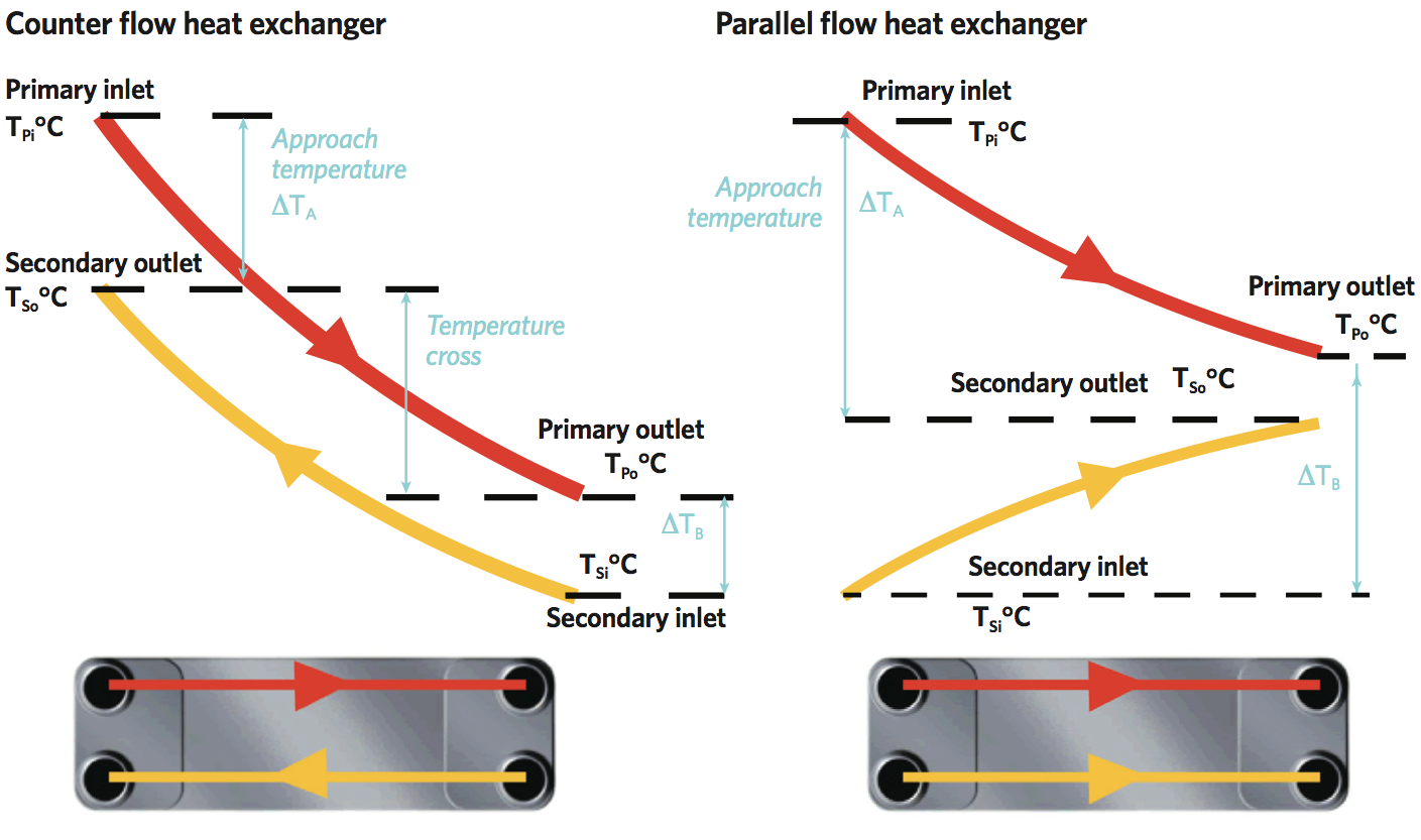
In a parallel flow exchanger both fluids in the heat exchanger flow in the same direction.
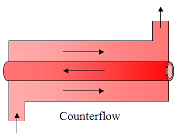
Counter flow heat exchanger equations.
Heat Exchanger Flow Cross Flow Parallel Flow Counter Flow Heat Exchangers Bright Hub Engineering

A Counter Flow Heat Exchanger With The Temperature Profile Download Scientific Diagram

Heat Transfer L32 P2 Temperatures For Parallel And Counterflow Heat Exchangers Youtube

Counter Flow Heat Exchanger Outlet Temperature Bio Youtube

Parallel Flow And Counter Flow Heat Exchanger
How To Decide Whether The Given Shell And Tube Heat Exchanger Is A Counter Flow Or Parallel Flow Quora
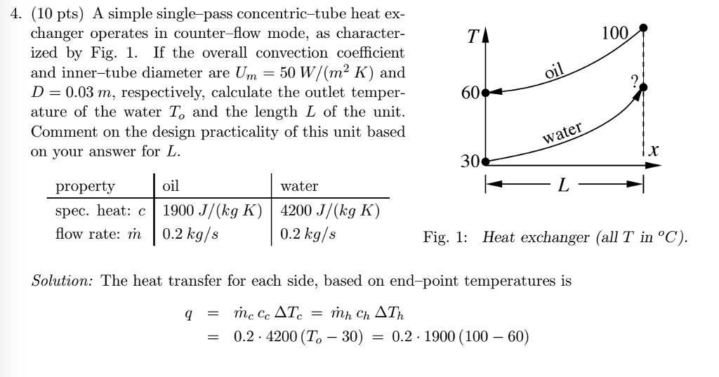
Solved A Simple Single Pass Concentric Tube Heat Exchange Chegg Com
Understanding Heat Exchangers Cross Flow Counter Flow And Cross Coun
Heat Transfer Heat Exchangers For The Mechanical Pe Exam
Engineers Guide Double Pipe Heat Exchanger Experiment
Solved 4 A Shell And Tube Heat Exchanger With Single She Chegg Com
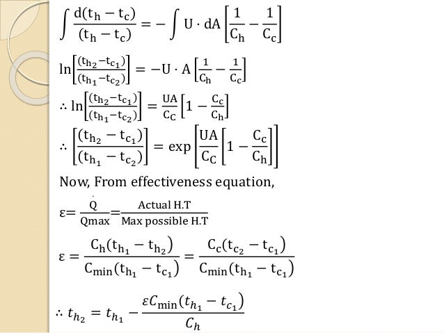
Effectiveness For Counterflow Heat Exchanger
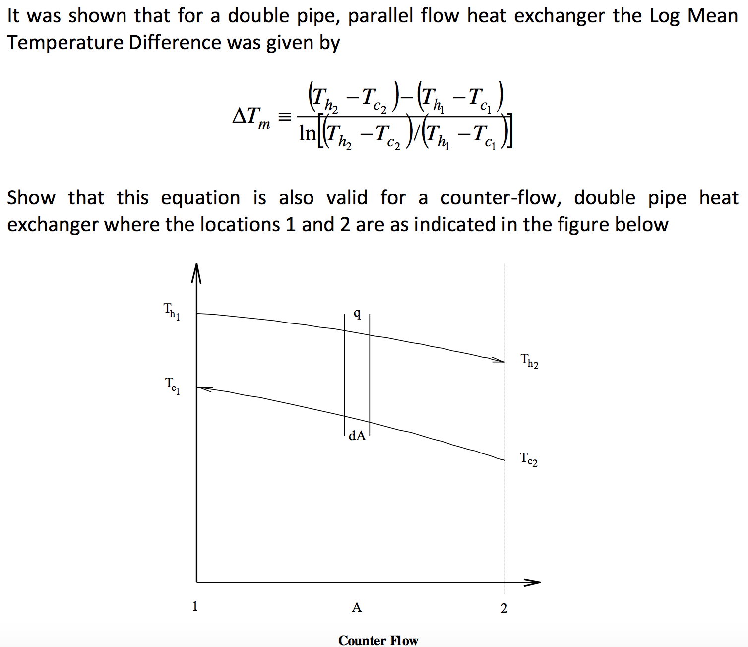
Solved It Was Shown That For A Double Pipe Parallel Flow Chegg Com
Parallel Flow Heat Exchangers
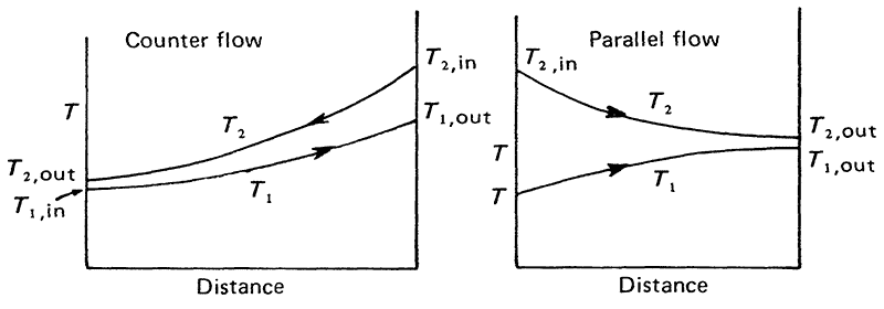
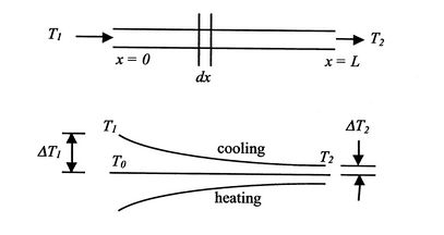
Types Of Temperature Change Pattern Heat Exchanger Design Handbook Multimedia Edition
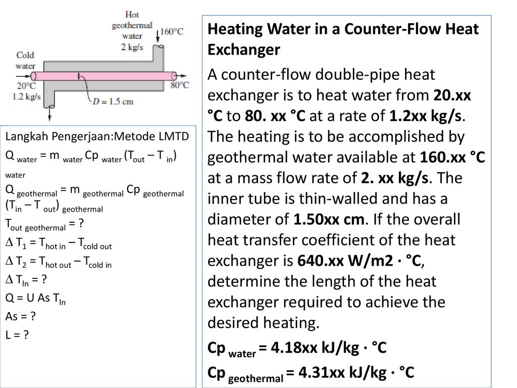
Perpindahan Panas Heat Exchanger Ppt Download
Basic Chemical Engineering Operations Double Pipe Heat Exchangers Counter And Parallel Flow Heat Exchanger Temperature Profiles U Type Or Hairpin Constructions Design Calculations
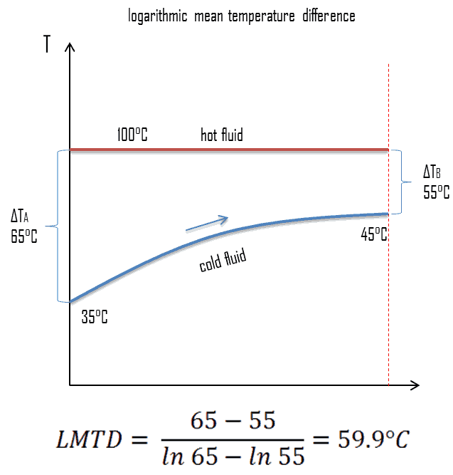
What Is The Lmtd In Heat And Mass Transfer Quora
1
Heat Exchanger
What Is Heat Exchanger Analysis Performance Calculation Definition
Module 118 Right Sizing Brazed Plate Heat Exchangers Cibse Journal
Heat Transfer Efficiency
The Black Box Model Of A Double Tube Counter Flow Heat Exchanger Springerlink
Source : pinterest.com
